How Do Electric Trailer Brakes Work? Magnets, Shoes and Drums Explained
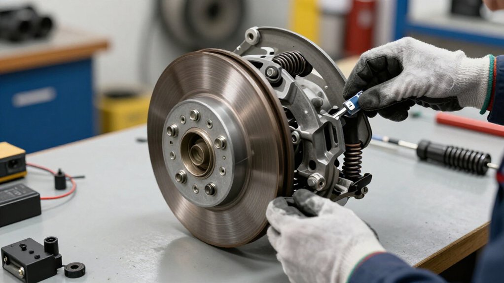
When you press the tow vehicle’s brake pedal, the controller sends DC current to each trailer brake magnet. The energized magnet pulls an actuating arm toward the armature plate, overcoming return springs and pushing both shoes outward.
Their linings press against the rotating drum, creating friction that slows the wheel.
In forward motion, the leading shoe can self-energize, increasing braking force. Proper adjustment and balanced current help keep braking predictable.
More detail follows on setup.
Magnet, Shoe, Drum Sequence
When the brake controller sends DC power, it energizes the electromagnet inside the drum assembly. You’ll follow the braking sequence directly from that signal to wheel deceleration. As current flows, the magnet attracts and pulls the actuating arm toward the armature surface, overcoming the return springs. The arm then pushes the primary and secondary brake shoes outward.
Their friction linings press against the inside face of the rotating drum. Because the drum turns with the wheel, friction between the linings and drum resists rotation and slows the wheel. That resistance creates the trailer’s braking force and helps prevent hub-and-drum rotation. As the controller increases electrical signal intensity, the assembly can apply greater braking force. Heat-resistant lining material and shoe-and-drum action support consistent braking.
Inside the Armature Plate
Inside most electric drum brakes, the magnet’s face contacts a flat armature surface inside the drum. When current energizes the coil, magnetic attraction draws the magnet toward the plate and initiates lever movement.
You rely on clean, flat contact for even force; grooves, scoring, corrosion, or uneven wear can limit it. Inspect the magnet face for even wear and check the plate with a straightedge. Heat, oil, grease, or storage rust can roughen the interface. A damaged plate may harm replacement magnets and reduce braking force when the magnet draws current.
| Condition | What you check | Possible effect |
|---|---|---|
| Clean surface | Full contact | Even attraction |
| Grooves or scoring | Interrupted contact | Weaker force |
| Corrosion or residue | Rough interface | Uneven braking |
| Damaged plate | Magnet wear | Reduced output |
Brake Response at Low Speeds
At low speeds, electric trailer brakes respond as soon as the tow vehicle’s brake switch closes and the controller sends DC current to the magnets. That current creates an immediate magnetic pull, so you can feel braking begin. At crawl pace, the slowly turning drum gives the actuating arm time to bring the shoes firmly into contact.
If controller gain is too low, the magnets may not receive enough current to produce force; you may notice weak or delayed braking. A hum while brakes should be off can signal that the brake circuit is energizing the magnets, risking unintended application. For reliable response, keep mechanical clearance correct and drum and armature surfaces clean and flat. Contamination or poor adjustment can prevent shoe contact.
Self-Energizing Shoe Action
When the magnet actuates the lever, you’ll see both shoes press against the drum, with the leading shoe creating the strongest self-energizing effect.
As the drum rotates forward, friction draws that shoe more firmly into contact and adds braking force beyond the magnet’s pull. In reverse, the shoe geometry changes how friction assists braking, so the assembly must maintain effective contact in both directions.
Shoe-to-Drum Contact
Once the shoes contact the drum, friction between their linings and its machined surface slows the wheel by converting rotational energy into heat. When your controller sends DC current to the electromagnet, it pulls the actuating arm, which pushes both shoes outward. Correct clearance lets each lining meet the drum evenly.
The rotating drum can drag shoe surfaces into rotation, helping clamp them harder as braking force rises; this self-energizing effect supports stopping in either direction, depending on design. You’ll want to inspect for rust, scoring, uneven wear, and greasy linings because these defects reduce friction and can cause weak or uneven braking during stops.
| Contact condition | Effect | Check |
|---|---|---|
| Flat, clean face | Consistent bite | Inspect drum |
| Grooves or grease | Weak, uneven braking | Correct surface |
Forward Energizing Action
As the drum rotates forward, it tends to pull the leading shoe tighter against its inner surface, increasing braking force without a matching increase in controller output. This self-energizing action begins only after your brake controller sends power to the magnet coil. The energized magnet attracts the armature, moving the actuating arm and pushing both shoes outward until their linings contact the drum.
Forward rotation then helps drive the leading shoe more firmly into contact, adding friction to the force established by the magnet. You get greater braking effect without requiring a proportional rise in electrical input. The shoes still depend on the magnet for initial actuation, so inspect magnet-to-armature contact and shoe clearance. A clean, flat armature surface and correct adjustment help preserve consistent forward energizing action; wear or uneven contact can reduce it.
Reverse Braking Differences
Reverse rotation changes how the primary and secondary shoes press against the drum, so the same magnet current can produce a different braking force. In reverse, friction between each shoe and the drum feeds back through the actuating lever. As contact forces shift, the lever may drive one shoe into a more effective biting angle, increasing brake effort without more magnet current.
This self-energizing action makes torque direction-dependent, although electrical magnet energization stays constant.
Most electric drum brakes can stop in either direction, but reverse braking may feel stronger than forward braking. You might need to adjust controller gain to maintain predictable stops. Inspect shoe wear and set clearances correctly; uneven wear or excess clearance can exaggerate reverse bite, cause lockup, or weaken braking despite correct magnet power delivery. If you notice a difference, check adjustment before compensating with controller settings, because gain can’t correct mechanical imbalance reliably.
Axle Load and Brake Balance
Match your brake setup and controller gain to the trailer’s loaded GTM, since heavier axle loads need more braking effort. Adjust and wire each axle so its brakes apply similar torque at the same time, keeping the trailer tracking straight.
Check for worn shoes, damaged drums, or poor grounds to prevent uneven braking and brake wear.
Matching Brakes to Axle Load
For effective stopping, choose electric drum brakes, such as 7×1¼-, 10×2¼-, or 12×2-inch assemblies, and magnets rated for the axle load, while keeping total current within the controller and wiring capacity.
Check that each assembly matches your axle, hub, drum, and wheel; correct shoe clearance and actuation geometry let the brake work as designed. Don’t use controller gain to mask an overloaded axle, worn shoes, or contaminated linings.
| Axle/load | Assembly | Magnet current |
|---|---|---|
| Light | 7-inch | 3.0–3.2 A |
| Higher | 10–12-inch | 3.2–4.0 A |
| Tandem | Same type/spec | Adjusted evenly |
At 12–13 V, compare magnet demand with the controller and wiring’s capacity; totals rise as you add brakes. For tandem axles, fit matching brake specifications and maintain equal adjustment and armature surfaces, so neither axle carries disproportionate work. Verify current and fitment before towing.
Balancing Braking Force
Brake balance is how evenly your trailer’s braking force is shared between axles, and it should reflect the load each axle bears. Set your controller’s gain so each axle receives braking power matched to its portion of the trailer’s gross trailer mass and its braking demand. If one axle carries more weight but gets the same braking gain as a lighter axle, the lighter axle may lock first while the heavier axle stays under-braked.
That mismatch can increase stopping distance and reduce control.
Match brake assemblies to the drums and shoes, since size determines the magnet current required for effective braking. At about 12–13 volts, 7-inch magnets typically draw 3.0–3.2 amps; 10- or 12-inch magnets draw about 3.2–4.0 amps. Ensure every brake is correctly adjusted: electrical power can’t compensate for mechanical imbalance.
Preventing Uneven Brake Wear
To prevent uneven brake wear, distribute the trailer’s load so each axle carries its intended share of the Gross Trailer Mass (GTM). An overloaded axle makes its magnets work harder and overheat, accelerating lining wear. Set braking force so each axle’s left and right sides match its load. Imbalance makes one side grab while the other brakes weakly.
Adjust the proportional controller’s gain: excessive gain can lock or drag a wheel, polishing or warping its drum and wearing shoes unevenly. Check clean, corrosion-free grounds and proper wiring on both sides; each magnet needs the expected current: about 3.0–3.2 A for a 7-inch magnet, up to 4.0 A for larger magnets. Inspect adjustment, oil or grease contamination, worn linings, and scored armatures or drums; uneven contact concentrates shoe wear.
Backing on Steep Boat Ramps
When you back down a steep boat ramp, the brake controller sends proportional DC power to the trailer’s brake magnets as soon as you press the pedal, prompting each magnet to pull its actuating arm and press the brake shoes against the drum. Each 12V electric brake magnet energizes an electromagnet inside the drum, pulling the actuating arm and forcing the primary and secondary shoes outward against the armature surface. Friction between linings and drum slows the trailer wheels.
Set controller gain to suit the grade without causing lock-up. Where fitted, self-adjusters maintain shoe-to-drum clearance during reverse stops. Weak braking, dragging, or an unwanted hum can indicate wiring, grounding, or controller setup problems, especially as ramp demand changes quickly. Check these systems before backing.
Heat Fade on Descents
Long descents make repeated electric-brake applications convert motion into heat through friction between the shoes and drum. As drum and lining temperatures rise, the shoe material’s braking coefficient can fall. You’ll notice heat fade: braking weakens even while your controller sends current. Excessive gain or current can increase electromagnet force and heat the shoes and drum faster than needed to hold a safe speed.
Use controlled, proportional braking instead of repeated full-power stops. Apply steady pressure and, when traffic and terrain allow, take brief cooling periods. If fade occurs, let the brakes cool before relying on them heavily again. Cooling helps the drum’s armature surface and friction material regain their ability to produce consistent friction against the drum, restoring more predictable braking performance.
Setting Brake Shoe Clearance
Set brake shoe clearance by backing off the adjuster until both shoes sit evenly away from the drum’s armature surface without rubbing. Then rotate the hub by hand. You should feel free movement, with only slight resistance when the shoes reach correct position; continuous scraping signals contact that’s too close.
- Keep the gap even so the magnet can pull the lever smoothly, allowing primary and secondary shoes to expand outward and generate friction.
- If you’re too tight, constant contact can overheat the shoes; too much clearance delays drum contact and weakens or postpones braking.
- Recheck clearance during routine service because shoe wear and drum or armature condition change over time; adjust it to suit the surface condition and preserve consistent braking response across stops.
Check Brake Controller Wiring
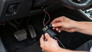
Because electric trailer brakes need controlled DC current, not just brake-light power, verify that the brake controller’s output reaches the magnets through the correct 7-way connector circuit.
Check wiring and connector pinout, especially if you use a 4-flat-to-7-blade adapter such as part #47185. A wiring error can send voltage to the magnets at the wrong time or reduce braking. Each magnet draws a few amps: about 3.0–3.2 A for 7-inch brakes and 3.2–4.0 A for 10- or 12-inch brakes at 12–13 V.
If your brakes hum when you aren’t braking, inspect controller wiring, connector compatibility, and ground connections. Test the magnets first, then examine the controller and wiring. Check the plug for corrosion or damaged wires; persistent faults may require rewiring a 6-way connection.
Conclusion
Understanding the magnet, armature plate, shoes, and drum helps you diagnose how electric trailer brakes respond and where problems begin. Keep shoe clearance correct, verify brake-controller wiring, and match braking force to axle load.
Remember that low-speed response, steep ramp backing, and heat buildup on descents can affect performance. Inspect and adjust your brakes regularly, and test them under safe conditions. These checks help you maintain consistent braking and reduce wear on your trailer.
Tongue Jack Rating Calculator
Estimate tongue weight from trailer weight and a cited 10-15% range, then check whether your tongue jack's rating covers it.
Flat Tow vs Tow Dolly Selector Quiz
Five-question quiz that routes you to flat towing, a tow dolly or a car trailer, with a weight check and owner's-manual check lists.
Trailer Tire Size Decoder & Wheel Fit Checker
Decode a trailer tire size, get its diameter, compare a replacement size and check rim size, lug count and bolt circle.